EIA/10BaseT Cable Tester
Model MCT-10BT
The MCT-10BT is an economical, one-step continuity tester to quickly verify the integrity of computer network cables.
 Instantly verify computer network cables
conforming to the popular EIA or 10Base-T standard. The EIA standard specifies
four pairs of wires connected between pins 1-2, 3-6, 4-5, and 7-8 of the 8-pin
modular RJ-45 connector; 10Base-T is a subset of EIA with only two pairs,
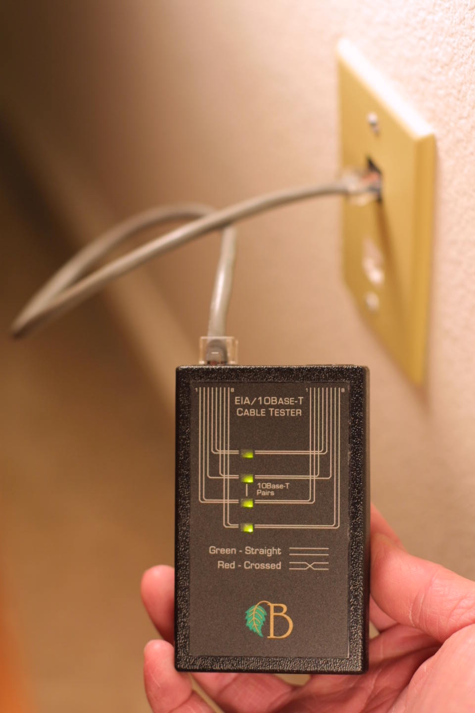
connected to pins 1-2 and 3-6. Four bicolor LED's on the tester correspond
to the four conductor pairs of the cable. If the wires in a pair are wired
straight through, the connection is shown in green; if the wires in the pair
are crossed (an error), the light is red. No light means that at least one
wire of the pair is not connected.
Instantly verify computer network cables
conforming to the popular EIA or 10Base-T standard. The EIA standard specifies
four pairs of wires connected between pins 1-2, 3-6, 4-5, and 7-8 of the 8-pin
modular RJ-45 connector; 10Base-T is a subset of EIA with only two pairs,
connected to pins 1-2 and 3-6. Four bicolor LED's on the tester correspond
to the four conductor pairs of the cable. If the wires in a pair are wired
straight through, the connection is shown in green; if the wires in the pair
are crossed (an error), the light is red. No light means that at least one
wire of the pair is not connected.
Network technicians and cable installers will also find it a handy addition to their tool kit. Two of these testers acting together may be used for end-to-end testing of installed cables. Attach the remote end of the cable to the right connector of one tester, and the local end of the cable to the left connector of a second tester. Connected pairs will be indicated on the local unit.
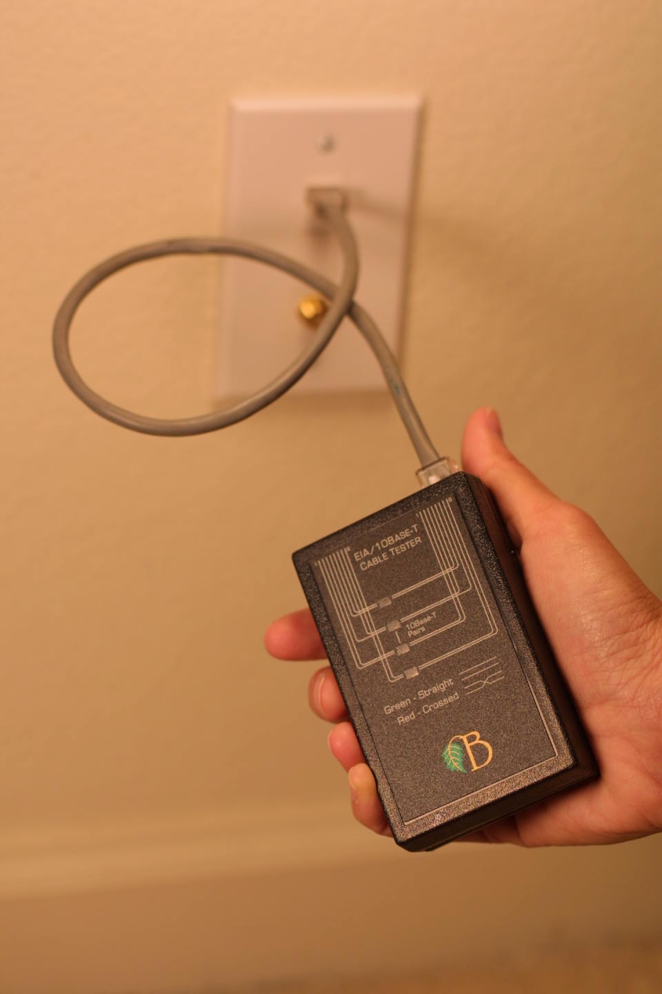
The cable tester is housed in a 1" x 2.4" x 3.8" plastic case, with power supplied by a 9-volt battery. Attachment of a cable activates the unit; when a cable is attached, the battery voltage is applied across the conductor and shield. The tester should NOT be attached to "live" cables, or damage to connected equipment may result. Disconnect both ends of the cable before attaching to the tester.
|
|
|
|
|
http://www.BirchT.com |

To test free cables...
|
|
The innermost pair (pins 4-5). |
|
|
The second innermost pair (pins 3-6). |
|
|
The leftmost pair (pins 1-2). |
|
|
The rightmost pair (pins 7-8). |
Attach each end of a cable to the tester. Each pair of wires in the cable has a corresponding LED which will light if the pair is present. A green light indicates the wires in the pair are wired straight-thru (e.g. pins 1 and 2 on one end are connected to pins 1and 2 on the other end.) A red light means the wires in the pair are crossed (e.g. pins 1 and 2 on one end are connected to pins 2 and 1 on the other end.)
Common network cable configurations are shown below:
|
Cable Type |
Connections |
Indicators |
Notes |
|
10BaseT, 100BaseT, etc. |
1,2 - 1,2 |
|
Pairs 4-5 and 7-8 are often connected on 8-wire CAT-5 cabling, but these pairs are not normally used in an Ethernet environment. |
|
10BaseT, 100BaseT, etc. Crossover Cable |
1,2 - 3,6 |
|
MCT-10BT does not differentiate between normal 10BaseT cables and “crossover” cables. If the wires in a pair are reversed, an error is indicated with a red light. A good cable will show green lights whether the pairs are normal are crossover. |
|
Token Ring |
3,6 - 3,6 |
|
|
To test installed cables...
Attach two testers to each end of the cable as shown below:
|
|
|
|
Local Tester |
Remote Tester |
|
(use left connector) |
(use right connector) |
The condition of the cable is shown on the local tester.